Portable Passive Range of Motion


Using an existing wheelchair multi-angle computer monitor mounting system
designed by BlueSky Designs, we would like to develop an independent range of motion (iPRoM) device for patients in their early stages of therapy. The system would be designed to guide patients through PRoM exercises prescribed by their physical therapist in the convenience of their own homes.
OUR TECHNOLOGY
OUR VISION
While the outlook for patient recovery has improved dramatically, research shows that the more regular physical rehabilitation patients recieve, the better the outlook of their recovery. As such it is important that patients undergo the rehab process 3-4 times each week. For many patients, with little to no remaining motor function in their upper limb, it is imperative that they undergo passive range of motion (PRoM) therapy as soon as possible following a stroke, until they are able to begin active range of motion exercises, in order to prevent muscular atrophy and preserve flexibility and mobility of their joints.

OUR STORY
We are a group of three undergraduate Biomedical Engineers completing our final year at Washington University in St. Louis. Our senior design project aims to improve the recovery time and extent of recovery for people who suffer paresis resulting from stroke or any other other acute neurological impairment.

ABOUT US
SCHEDULE

OUR GOAL
01 / Stroke
Stroke occurs when part of the brain is deprived of oxygen as a result of a brain clot or hemorrhage. According to the CDC, about 795,000 people will experience a stroke this year, and it remains the fifth leading cause of death in the United States.
02 / Life After Stroke
While survival rates are improving, stroke remains the leading cause of disabilities in the United States. Paresis, or partial paralysis, is common among people who have suffered a stroke. Paresis from a stroke often results in weak or no motor function on one side of the body.
03 / Stroke Rehab
Research has shown that individuals who have suffered from a stroke that resulted in paresis, recover significantly more of their lost motor function if they undergo some amount of physical rehabilitation. Current rehabilitation involves passive and/or active range of motion exercises guided by a physical therapist.
PROGRESS
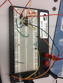
An H-Bridge circuit was created to control our DC gear motor that will be used for our two custom joints. An H-Bridge was necessary due to the fact that the polarity of the motor needs to be switched in order for the motor to change directions. The H-Bridge will take in the voltage level desired to control the motor, and depending on the input on other pins, the bridge will switch the polarity over the two motor leads. The final circuit layout can be seen below. Our microcontroller controls the pin input on the other H-Bridge pins that controls the polarity. This enables for the control of the motor to be driven by software.

2) Custom Joint Hardware Design
1) 3-Joint Solution Design Model
3) Custom Joint Software Design
A script was created which will have several functions. The first function will enable the user to pick which joint they want to exercise. Then, they can select how many degrees of movement they want to exercise on that specific joint. After these selections are made, another function is called which actually moves the motors for the desired exercise and degree input. As of now, the code still needs software safety features along with the addition of more joint exercise options. Images of the user interface will be uploaded soon.
4) 3-D Printing Progress
1) MATLAB Mapping Model
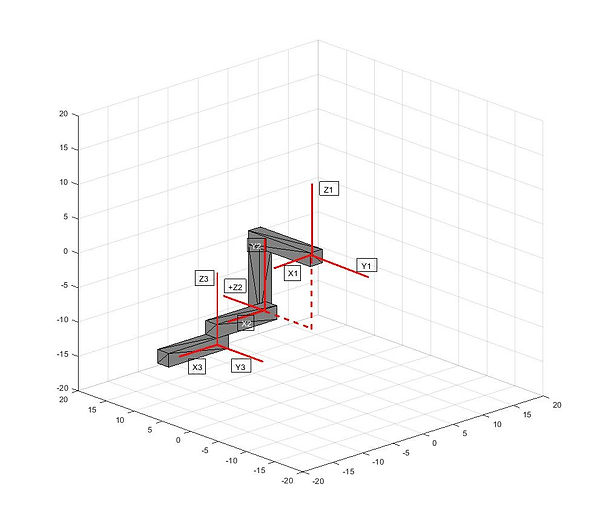
A MATLAB transformation simulation was created and used to prove that the desired rotation of each joint for our PROM device is possible using these simple transformation matrices. The MATLAB code would be attached, but scinote does not accpet m files. It wil be uploaded as text. Both the function and the main script need to be in the same folder for the function to run. The script runs on the basis of transforming points in each individual joint space to the main base frame. This is a method to determine the position of all joints relative to each other while they are moving. This process uses transformation matrices from each joint space to move the points to the base frame. This process can be implemented in the coding of our device with the given encoder values converted to angles of rotation. The next step is to update the rotation matrices to a more generic, formal form. Also, the frame description for the updated transformation matrices is attached to these results.
The maximum possible range of motion of each joint was tested using the simulation. For example, for the elbow range of motion, a simple for loop was used to rotate the third link of the system inward 135 degrees and then back to its original position. This same method can be used to control the rotation around each joint, depending on what human joint is needed to be exercised. In addition, the degrees of rotation can easily be adjusted through the settings in the code, depending on the patient’s needs. This simulation proves that a similar control method can be used to control our mechanical PROM device. Each motor, which represents a joint on the simulation model, will have an encoder which returns an angle of rotation, theta. The angles that the encoders return will be entered into the code and transformation matrices, and therefore used to map the exact position of each link. Knowing the exact positioning of each link relative to the base frame and each other is a necessity for the safety of the device. By continually monitoring the position of each link, the code can compare the desired position and movement of the device to the actual position, which creates a continuous feedback loop which acts as a software safety check. In addition, planes can be defined in which any link should not cross. If any point that is being mapped crosses one of these planes, the entire system can be stopped to prevent injury to the patient and to the device. In review, the encoder values will be used to map the position of each link, which will then be used in a control loop which constantly checks to make sure the device is within a specified safety range.
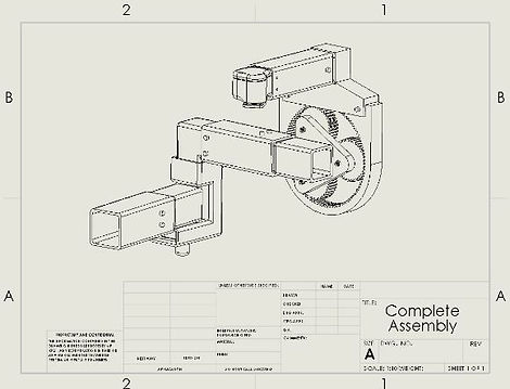
This CAD drawing represent the final design of the first prototype. Actual demo coming soon!
GET IN TOUCH
Tel: 555-555-5555
Fax: 555-555-5555
1 Brookings Dr.
St. Louis, MO 63130